
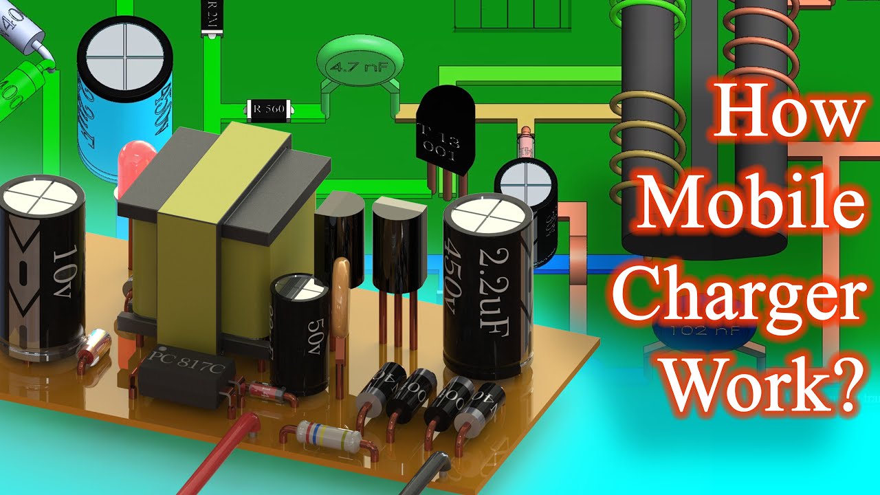
We use our smartphone everyday but have you ever wondered how your smartphone charger works you would know that charger converts AC to DC but it's not that straightforward first it converts AC to DC then again back to AC and then finally to DC today. We are going to see how the charger does this and why are there intermediate steps this is a normal charger that converts 220 volts AC to 5 volts DC let's see what's inside now we can see all the electronic components used in it there are diodes capacitors. Transistors. And resistor also there are resistors below the PCB.
This is a transformer and this is an opto coupler once power is supplied it turns on to understand it better let's rearrange the circuit. Now we can see all the components and connections this red wires phase wire and the black is neutral. First we have is a resistir by observing the color bands and reference table we can see it's 260 kilograms this is a fusible resistor which prevents damage from overloading then there is a bridge rectifier made by 4 of 1 and 4007 diodes and a filter capacitor of 450 volts and 2.2 micro ferret this circuit converts AC to DC.

This is an oscillator circuit this converts DC back to high frequency AC 15 to 50 kilohertz we can see the values of the components. This is transistor S. 8050 this is its pin configuration. And this is transistor 13001 this is its pin configuration. This is a diet it looks like Zener diode but it's a fast switching diode 1 N. 4148 and a capacitor of 50 volts 22 micro ferret this is AC to DC converter for the photo transistor in opto coupler it forms a circuit like this. This is the transformer it has 3 windings primary secondary and auxiliary winding wrapped around the corner it is used to step down the voltage the auxiliary winding is used to run the oscillator circuit. Then we have a Schottky diode 1 N. 5819 with a capacitor of 10 volts 470 micro ferret to convert AC to DC and LED for indication.
Also there is a feedback circuit that consists of an opto coupler PC 817 C. and 4.2 volts Zener diode. This is an opto coupler it is used for transmission of signal without contact on the right side we have is an infrared LED and on the left is photo transistor when the LED turns on its light turns on the base of photo transistor turning it on this capacitor is of 102 nano ferried used for safety purposes it is connected between primary and secondary grounds to stop electromagnetic interference.
Let's turn it on and see an action the green wires carry the positive voltage and the blue wires carry the negative voltage or ground also we can see the voltage in the circuit on the graphs we have the input of 220 volts 50 hertz AC this is a bridge rectifier it converts a seat to fluctuating DC as we can see this fluctuating DC filters from the capacitor and becomes almost pure DC we can see we have is DC in the circuit. Now this current passes from the 2 mega ohm resistor to the base of T. one turning it on this transistor isn't fully turned on because of the resistance it turns on partially due to partial turning on of the transistor low current passed from the primary winding of the transformer this induces a low voltage in the auxiliary winding the induced voltage now charges the capacitor and then the capacitor fully turns on the transistor as the transistor is now fully on it allows the current to flow through itself now this turns on the transistor T. 2 this shuns the base of the T. one turning it off as the T. one turns off the flow of current to the T. 2 is cut off now the current flows to the base of the T. one and the cycle repeats this happens at 15 to 50 kilohertz which is 0 times faster than the rectifier circuit hence you would see that the rectifier circuit is stopped. At the same time the voltage from the auxiliary also turns the diode on and charges the capacitor and flows to the opto coupler. This diode and capacitor convert the AC from the auxiliary coil to DC for the opto coupler.
The current is also induced in the secondary winding this is converted to DC by a Schottky diode and a filter capacitor it is indicated by the L. E. D.. But what if the voltage is more than 5 volts. Hence we have is a feedback circuit as we reach 4.2 volts the Zener diode turns on allowing current to flow to the opto coupler it also drops the voltage by 4.2 volts hence the LED of the opto coupler doesn't turn on. D. LED requires 0.8 volts to turn on when the voltage reaches more than 5 volts this turns on the LED of opto coupler the light of the LED turns on the photo transistor of the opto coupler allowing the current to flow to the transistor T. 2 this turns on the transistor T. 2 shunting the first and stopping the flow of current in the primary winding also the voltage in the secondary side of transformer drops below 5 volts turning off the Zener diode and opto coupler and the circuit continuous to run normally.
Now you would have the question why not directly convert AC to DC than this this is because for the normal power supply which is at 50 hertz the size of transformer and the capacitors are large they cannot be mounted in a small charger like this hence in the charger the 50 hertz frequency is converted to 50 kilo hertz. This reduces the size of the transformer and capacitor required in the circuit so to change the frequency of AC first we have to convert it to DC and then again back to AC Now you know how the charger that we use daily works.
Post a Comment (0)